Quite a whie ago I posted my GA-40 lite design on wattkins.com. Others then also build the design and finally a member made a little PCB board for the design. He then sent me one of these boards totry out. however, instead of building another GA-40 lite I built this amp based a slightly on a Supro 1624.
Probably the main reason I chose the Supro is that the board is designed for a paraphase phase inverter which the Supro has, very similar to the GA-40. Pretty much all of the component values in the phase inverter are different but it was easy to adapt.
Overall it’s a fairly simple amp. I was going to do a preamp like the 1624 but I ended up doing something simpler and that could all fit on the PCB.
I’m using a 6N2P paralleled up front. After that I’m doing a take on the high pass filter that is present in the Supro. The Supro has a cap followed by a resistor to ground. I’m doing the same thing but using a pot for he resistor to ground. This turns the high pass filter into a bass control and it works pretty well.
I’m using the 500k volume pot with a 500p bright cap like the Supro along with a simple treble bleed tone control. After that it’s into the supro phase inverter which is where, I believe, the “Supro sound” really comes from. I’m using another 6N2P for the phase inverter.
The power tues are 6P1Ps. They seem to be seldom used in a guitar amp but they are cheap and sound pretty good.
The power transformer in an MPS 190.2 and with that i’m getting a plate voltage of about 260vdc.
The OT is a Hammond 125E configured for a 11.6k primary.
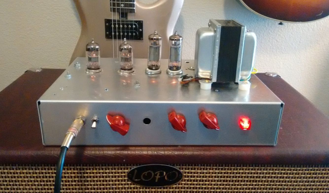
One nice thing about this PCB is the small size. I was able to fit everything in a fairly small chassis.
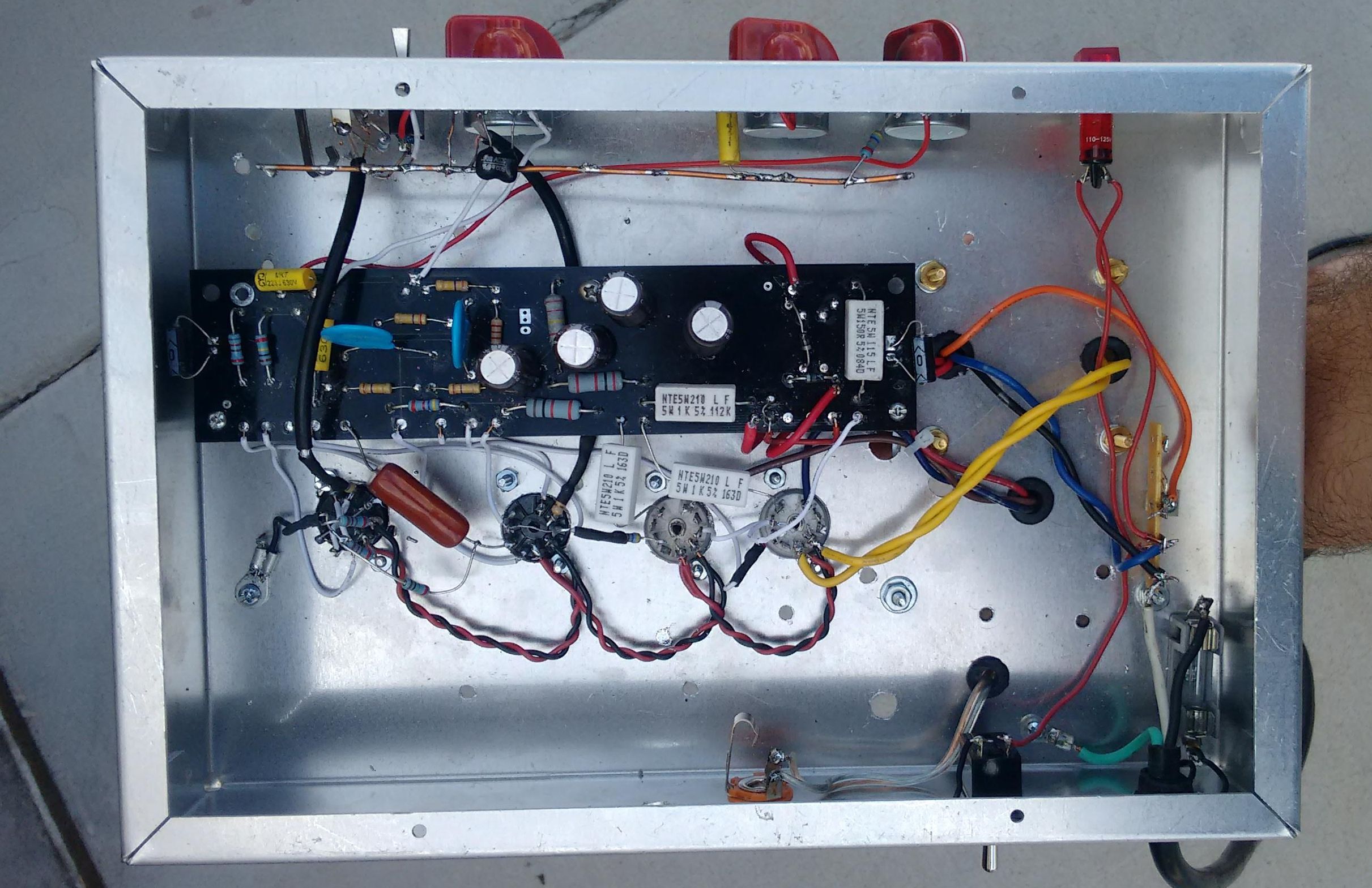
This is the PCB. You can sort of tell it’s been reworked a bit by me…
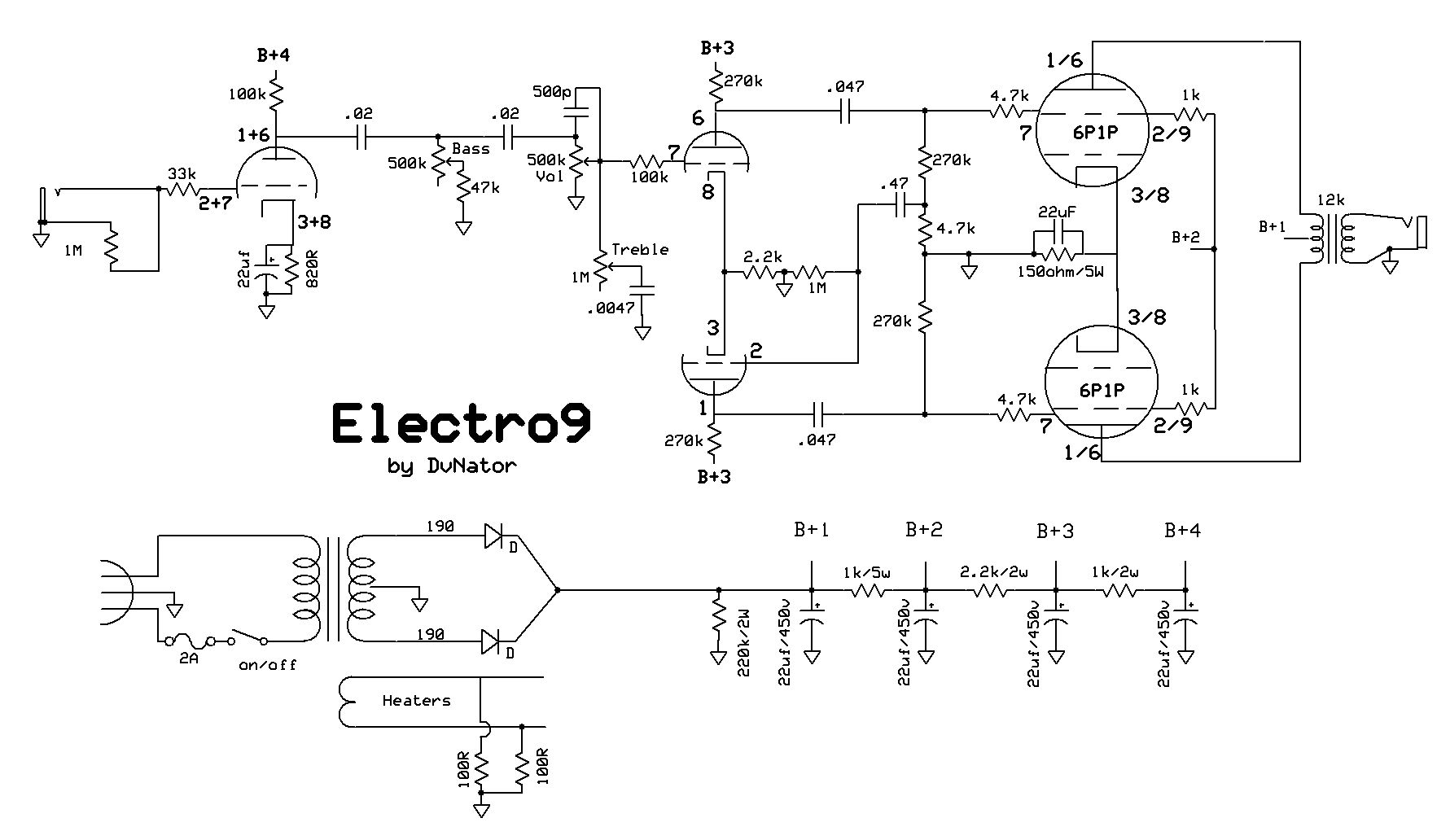
And this is the schematic:
And finally, a clip:
Update:
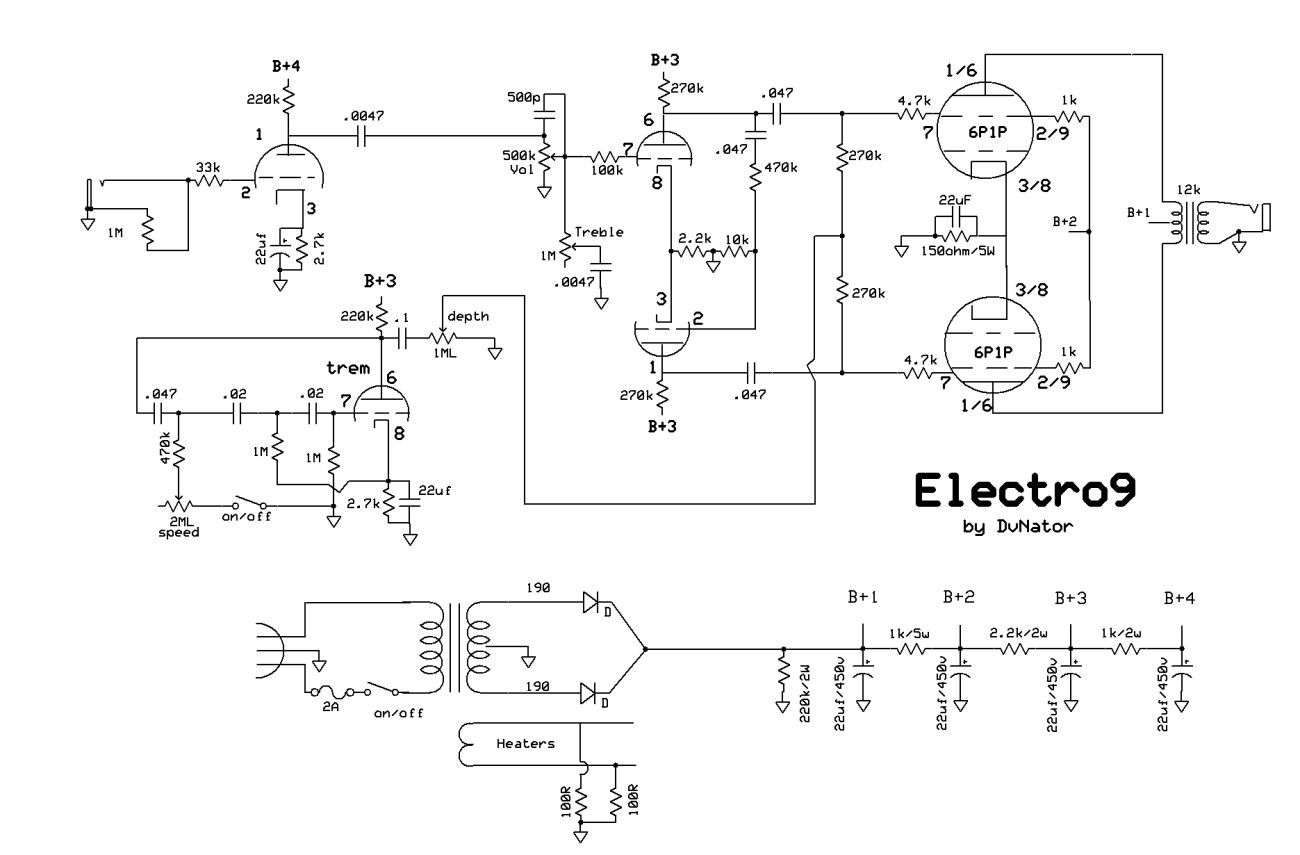
I decided to make a change with this amp and add tremolo. I like bias wiggle trems but did not see many examples of a bias wiggle trem and a paraphase inverter. Ampeg did it but the paraphase is a little different. So, with the Ampeg as inspiration, I tried seperating the power tube grid leaks, where the trem connects and the phase inverter. It seems to work great or at least as good as a bias wiggle works with a cathode bias amp.
Here is the updated schematic:
Leave a Reply
You must be logged in to post a comment.