This one came about when I wanted a versatile bedroom guitar amp. It had to be low wattage and be able to get clean and dirty sounds.
Based on those requirements I went with Russian 6F4Ps (ECL84 equivalents) again in push pull. They keep the volume down but are real pentodes and have that sort of tone. I could have gone with a triode output section but that wasn’t the sound I was going for. 6F4Ps are really cheap too. A pair in push pull probably puts out about 3 watts or so.
The design of the amp is very much like the JCM5E3 I made many years ago. I always liked it for a simple amplifier with a good Marshall sort of tone. The basic format is a JCM800 preamp with a plate driven tone stack and master volume off the third stage. The signal then goes into a split load phase inverter and then to the power tubes. Since the 6F4Ps have a triode in the bottle with the power tube those triodes make up the last gain stage and the PI. The amp just has only 3 tubes, one 6N2P (12AX7 equivalent) and 2 6F4Ps, total.
I’m using the standard Marshall 2.7k/.68uF combo on the first gain stage but I went with a 150k plate resistor to warm it up a little. After the first coupling cap is what started out to be a standard Marshall 470k/500p treble peaker. However I had an open hole in the front panel for a switch and I wanted some clean sounds so I came up with the handy option.
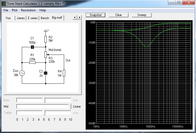
I split the 470k resistor into two 220k resistors in series. That doesn’t quit add up to 470k but it’s close enough for rock and roll. The junction of the two 220k resistors goes through a .002uF cap to one side of an on/off/on switch. The center of the switch goes to ground. In the .002 cap position it creates a bridged T mid cut circuit for a scooped mid that works great for clean tones. The bridged T was used in a bunch of old Gibson amps but is not seen much anymore. Here’s a good example of one after the first gain stage. The center of the switch is off so thats more or less the standard Marshall treble peaking circuit (440k instead of 470k but odds are no one could tell the difference). The other side of the switch keeps the treble peaker circuit and puts a 15k resistor parallel with the 10k cathode resistor of the second stage making it about 6k. Lowering the cathode resistor value here is a standard hot rodded JCM800 tweak and this gives a nice gain/saturation boost.
Here is a visual of what the first two switch positions do. The difference between the mid cut and the treble peaker is pretty obvious.
Then after the switch is the 10k stage with a simple cap and ground reference resistor going on to the 3rd stage. I went with a center biased, fully bypassed 3rd stage to drive the tone stack. Biasing hotter sounded a little fizzy to me. The cathodyne PI has the usual tricks to make it behave like the grid stopper before the PI and the big power tube grid stoppers. This format works well with the 6F4Ps because they are so sensitive you have to throw away gain or they sound sorta bad. With this design you have the tone stack throwing away gain before the power tubes so it works out well.
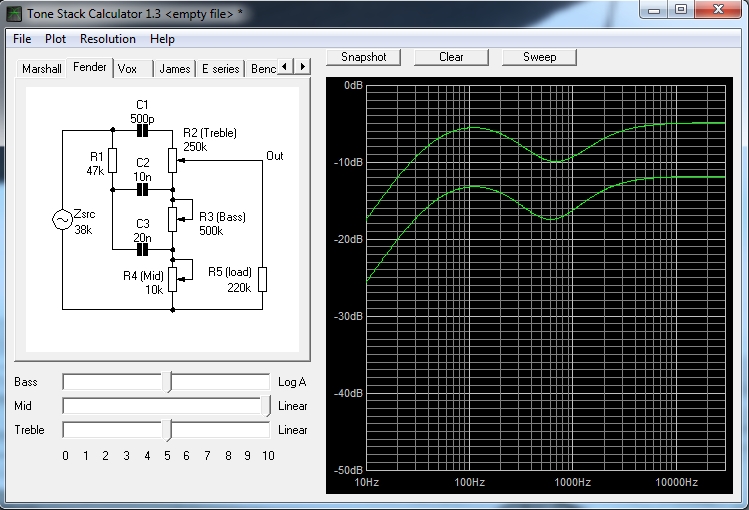
The tone stack was tweaked to be close to the Marshall JCM800 tone stack but without being connected to a cathode follower. On the graph below the top line is the Marshall tone stack and the one below is the one from this amp. The curves are about the same but the output is less because there’s not cathode follower.
The transformers I used were really easy on the wallet. I’m using an Edcor XPWR024 power transformer and a 70v line transformer for the OT. It’s a Speco that I’m not sure if it’s still sold but it might be this one.
I think the end result is a good sounding 3 watt amp that is easy on the neighbors.
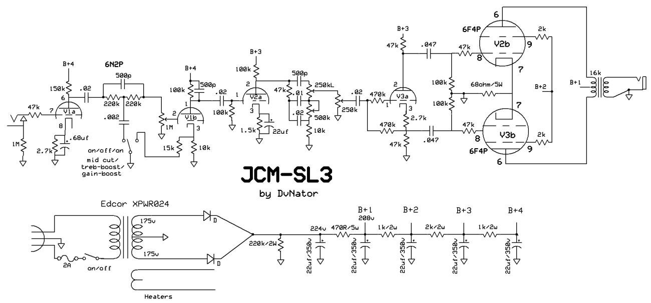
Here’s the schematic:
Lots of clips:
With a Les Paul cranked up. I didn’t plan the film noir lighting 🙂
With a P90 strat. You can get a good idea of what the switch does in this clip.
Hi! i love your website, chasingtone, i read every of the projects there. Im from Argentina (sorry for my English, its not my native language).
I want to ask you if you ever tried a quad push pull with theese 6f4p (ecl84). I’ve thinking about to build some circuit like the one on this video, using the other 2 triodes instead of the 6n2p (i know that them haves less gain) .
how many watts do you think i can get using 4x 6f4p?
Thanks you so much, i’ve learned a lot from you
Thanks, I’m glad you like the web site.
I’ve never tried more than a pair of 6F4Ps. I would guess you’d get about 8 or so watts from 4 of them. Using those triodes would likely work fine too but one thing that might be tricky is the the layout since the preamp triodes will be mixed with the power section.
iv’e build the circuit, with 4 ecl84, but using a classic marshall full tone stack, its kinda jcm800’ish . Nice gain, nice tone, very versatile. I’m going to add a spdt to switch between triode 1 and 2 to get some clean tones.
About the power, i’ve build several 6v6 push pull amps with 2 tubes, and this one is about 70% of that.
Here you can hear the result. Sorry for my English, its not my native language.
https://www.youtube.com/watch?v=L-6RvYR3It0
Yeah, that sound good! Nice work!
Great work! Would you share your layout, please?
i found them on mail sent to myself 2 years ago, i thought i dont have the files anymore.
Hope you like them. Any question mail me to facu.larabia@gmail.com
https://drive.google.com/file/d/1Vl9J4f-cTQ2NB06sTHV-_aedxtwZ9-Gd/view?usp=sharing
https://drive.google.com/file/d/1Vl9J4f-cTQ2NB06sTHV-_aedxtwZ9-Gd/view?usp=sharing
This 6n2p based amp souds really Great! Very good clean and overdrive, gonna try these tubes in diy jcm800 amp. Thats a low-voltage mod or special tone compensation? Can you tell me voltages B+3 and B+4, if its possible? Thanks!
I’m enjoying your website! Earlier this year I bought some 6F3Ps, which led to 6F4P, 6F5P, and 6F12P. Not content to stop there, I also rounded up some 6N2P, 6N9S (6SL7), 6P1Ps, 6P15-EV, 6P18P, and 6P43P-E. And just for good measure I also got some double beam-tetrode GU-17s and some 6P3S (6L6GT) and 6P7S (6BG6G). Oh, and some 6F6S, which oddly are more or less the same in Russian (6F6G).
Yeah, it’s an illness.
I’ve gotten as far as using the 6N2Ps and the 6P1Ps in an amp, and I like ’em a lot. I like your designs and may try one or two, or variations thereof. Keep building!
Hey! Big respect and thanks for all the projects here. I am planning to build an amp with 64fp tubes too and want to use a line OT. Would it be possible if you could show me a picture of how you wired the line OT? I think I understand how to set up the correct impedance but I want to double check.
Thanks!