This one came from the ashes of a different project that I didn’t stick with. It was a big bottle single ended amp that I decided would be better as push pull. I kept the PT and some of the filter caps and then embarked on complete redo.
I had not done much in the way of a Vox type amp and thought it was about time to do something with a Top Boost preamp. Not one to build something obvious I went with a a pair of 6L6s rather than EL84s for the power tubes. The real reason for that was the PT but I’m going to chalk it up to originality as well as seeing something similar at the Amp Garage called the Rockster.
Since this was a rebuild I didn’t really have room to add tubes other than the addition power tube. So in the interest of low glassware count I went with a MOSFET follower rather than a tube cathode follower. That allowed me to use one 6N2P for the two gain stages and just one additional 6N2P for the phase inverter.
I tried to first use cathode bias for the 6L6GCs but it didn’t seem to work very well with the power transformer. It got fairly hot so I went with fixed bias which worked better.
I didn’t go with the standard Vox tone stack. I had tried it in the past and the interactivity between the treble and bass drove me crazy. I used the same basic values but wired it up Marshall style and use a 25k mid pot. From working with Duncan’s tone stack calculator it is almost exactly the same frequency response when the controls are at noon.
I managed to squeeze a second “Normal” channel out of it. After the first triode I’m taking the signal through a big .1uF cap and into the other side of the phase inverter. It works pretty well as the two channels are in phase and can be mixed for some extra fatness.
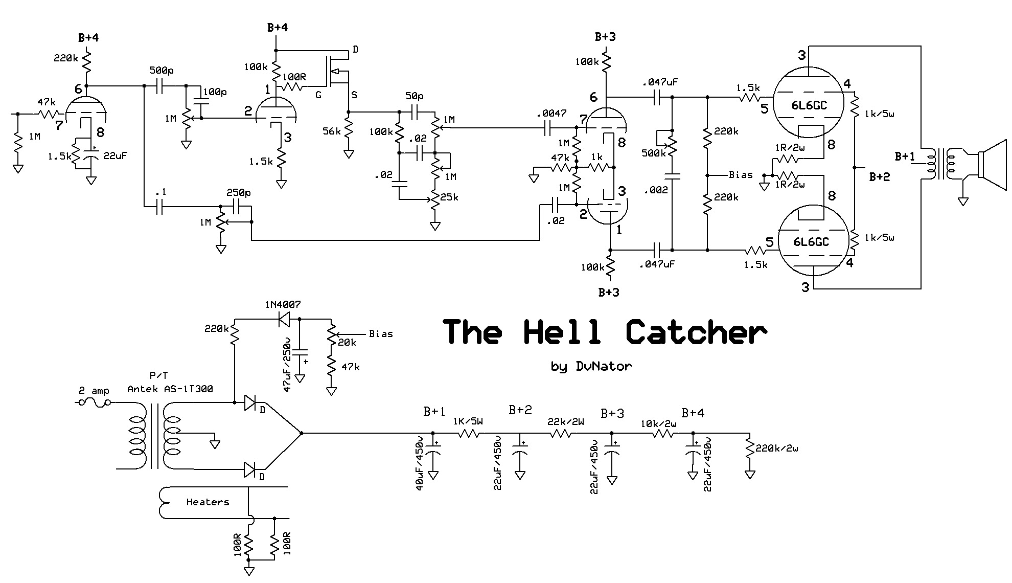
This is the schematic:
And here is a clip:
why do you use a 47k katode resistor in the pi ?
It’s not a cathode resistor, it’s a tail resistor. Notice the 1k resistor right next to it? THAT’S the cathode resistor!
This type of phase inverter, called a “long tail pair”, and it’s very common in most amplifiers out there.
Basically, one triode gets signal, the other is driven via cathode (since both are tied together and unbypassed), and the other triode amplifies this signal out-of-phase from the first triode. The tail resistor is what determines the balance between both outputs of the inverter (aka the gain of each triode). Lower tail resistor = lower balance, but this can be fixed by using different plate resistor values for each triode.
can you get any more gain out of it and more Marshall tone ? i have a bolt 60 With no preamp and it uses 6l6 tubes ,
If I was going to try to get a more Marshall tone out of this I would….
1) change the first triode to 100k plate with 2.7k/.68uF on the cathode.
2) change the cathode on the second triode to 820R/.68uF
3) change the tone stack to standard Marshall values
4) change the phase inverter from 47k/1k to 10k/470R
5) ditch the second channel idea and add negative feedback and a presence knob. 100k feedback resistor and a 5k/.1 presence knob.
6) change the first coupling cap from 500p to maybe .0047uF
I think that would do it.
well i want to get as much gain as i can from the 2 gain stages , and i want to reduce the Powertube gain because of the 6l6s i think i will use 22K7/ 470r in the pi,